Author: pa

2 Test Sections (8 m/s, 13 m/s)

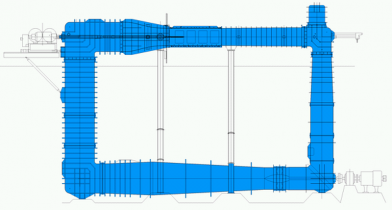
Kavitank_SchemaZeichnung
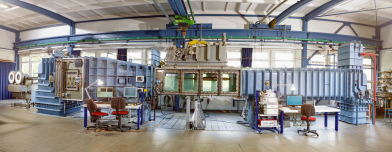
Freifahrt_K15A_SVA-Potsdam_2015_small

Main Parameters of the Sensors
Parameter R37 R35X
Components in x direction (x) [N] 800 500
Components in y direction (y1, y2) [N] 800
Components in z direction (z1, z2, z3) [N] 500


Main Parameters of the Dynamometers
Parameter J25 H36 R45
Propeller thrust Tmax [N] 3000 2000 400
Propeller torque Qmax [Nm] 150 100 15
Propeller speed nmax [s-1] 60 50 50
Shaft angle [°] +15 bis -10

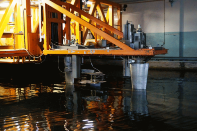
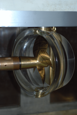
The SVA Potsdam operates the K15A cavitation tunnel from Kempf & Remmers. There are two measurement sections available. The length between the two vertical parts of the cavitation tunnel is 12 m, the height between the horizontal parts is 7 m. The impeller of the cavitation tunnel is powered by a 100 kW DC motor.

The cavitation tunnel has J25 and H36 dynamometers. Both dynamometers can be operated alone or together, so that tests with counter rotating and/or tandem propellers can be performed. In addition, the water- and pressure-tight R45 type inner drive dynamometer is available for special tests (i.e. overlapping propellers).

The velocity in the test section of the cavitation tunnel is determined from the pressure differential ahead of and behind the nozzle (Venturi principle). The pressure in the test section and the atmospheric pressure are also measured with pressure sensors.

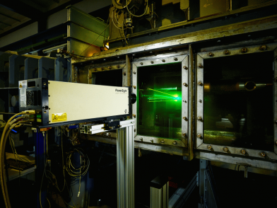
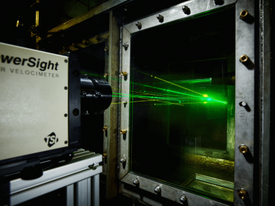
For the measurement of forces on profiles, lifting surfaces, nozzles and rudders, the R37 and R35x sensors are available. By default, local speeds are measured with a laser (Powersight LDV (TSI)). For the measurement of velocity fields, a PIV measurement system from TSI can also be used.

In the small test section, cavitation tests with propellers for fast ships, special tests such as measurements on profiles and wings, speed measurement with LDV or PIV, erosion tests and calibrations of speed measurement systems are predominantly performed.

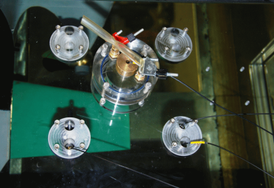
The investigation of the cavitation behaviour of propellers in the wake field of a vessel and the measurement of the propeller induced pressure fluctuations take place in the large measurement section of the cavitation tunnel. The simulation of the wake field, calculated for the full-scale Reynolds number, is made with a dummy model and additional screens [1], [2], [3], [4]. The H36 dynamometer is integrated in the dummy model. The dummy models are up to 2.60m long and geometrically similar to the ship in the stern area. Pressure sensors are arranged in the dummy model above the propeller. Standard in the SVA, the CFD calculated wake field of the full-scale model is simulated with a dummy model and additional screens.

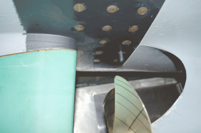
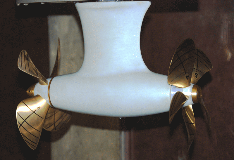
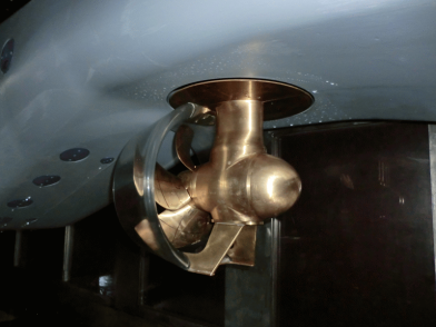
For the investigation of the cavitation behavior of thrusters, podded drives and Voith-Schneider propellers or steering propellers, special measurement systems have been developed. The same goes for power and torque measurements on individual blades of adjustable pitch propellers at cavitation similarity.

Please read more about the various tests and test objects in the Cavitation Tunnel here.

Technical Specifications of the Test Sections
Parameter Test Section 1 Test Section 2
Measurement section length 2600 mm 2600 mm
Measurement section area 600 mm x 600 mm 850 mm x 850 mm
Contraction ratio of the nozzle 5.96 : 1 2.93 : 1
Maximum speed in the test section 13 m/s 7.5 m/s
Variation of the measurement section pressure -970 mbar bis 1200 mbar -950 mbar bis 1200 mbar


Context Related References / Research Projects

[1] Selke, W., Heinke, H.-J.: Propelleruntersuchungen im Kavitationstunnel der Schiffbau-Versuchsanstalt Potsdam, Jahrbuch der STG, 84. Band, 1990
[2] Schmidt, D., Selke, W., Gerchev, G.: Comparative Joint Investigations in the Cavitation Tunnels of SVA and BSHC on the Prediction of Propeller-Induced Pressure Pulses, Schiffbauforschung 31 (1992) 1
[3] Heinke, H.-J.: The Influence of Test Parameters and Wake Field Simulation on the Cavitation and the Propeller Induced Pressure Fluctuations, Jahrbuch der Schiffbautechnischen Gesellschaft, 97. Band, 2003
[4] Kleinwächter, A., Hellwig-Rieck, K., Ebert, E., Kostbade, R., Heinke, H.-J., Damaschke, N. A.: PIV as a Novel Full-Scale Measurement Technique in Cavitation Research, Fourth International Symposium on Marine Propulsors, smp’15, Austin, Texas, USA, 2015

SUBPMM Test Stand

SUBPMM_Otter

SUBPMM_Zeichnung

Measurements with submerged bodies are performed on originals or copies in original size and scale models. The range of test objects extends from submersibles such as ROVs and AUVs to submarines and special investigations of marine life and divers.

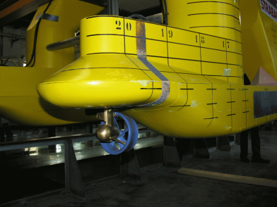
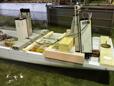
To determine the motion behaviour of underwater vehicles in the vertical and horizontal plane, and also for resistance and propulsion tests as well as wake measurements, the SUBPMM (Submarine-Planar-Motion- Mechanism) system is used. What is special about this system is that the measuring points of the forces are placed within the model and hence the influences of the towing device can be eliminated. The system is adaptable for model sizes from 1 to 6m and depths of 0.5 to 2.5m. For driving the models, enclosed motor dynamometer modules are used with different sizes to choose from.

For the determination of the motion behaviour of underwater vehicles, the simple drag motion of the model can be superimposed with an additional level of movement with the SUBPMM system. In addition, the angle of attack of the model as well as the control arms can be varied. Thus, it is possible to determine the coefficients for the equations of motion.

The SUBPMM system is also used for resistance and propulsion tests. For wake measurements a probe with pressure sensors is used which can be adjusted automatically.

In the R&D projects, “Scale Effects in Determining the Manoeuvring Behaviour of Underwater Vessels by Model Testing” [3], “Correlation of Resistance of Submerged Bodies” [1], “Interference Phenomena in Substructures of Submerged Bodies” [2] and “Influence of the Reynolds Number carried out in the Thrust Deduction Fraction”[4] Geosim-tests and calculations for underwater vessels for motion behaviour, resistance and interference phenomena were executed. The results of these studies are incorporated into the correlation for full scale predictions.


SUBPMM_CFD_Uboot SUBPMM_DIagramm SUBPMM_Nachstromrechen


Context Related References / Research Projects

[1] Grabert, R., Rieck, K.: Skalierung von Widerstandsversuchen mit U-Booten, VSM(2007)
[2] Nietzschmann, T.: Interferenzerscheinungen bei Substrukturen von getauchten Körpern”, FuE-Sachbericht (2012)
[3] Steinwand, M.: Maßstabseffekte bei der Bestimmung des Manövrierverhaltens von Unterwasserfahrzeugen durch Modellversuche, 2. SVA-Forschungsforum, Potsdam, 29. Januar 2009
[4] Hellwig-Rieck, K.: Einfluss der Reynoldszahl auf die Sogziffer, 4. SVA-Forschungsforum, Potsdam, 27. Januar 2011

Hydrophone Array

Lorem ipsum dolor sit amet, consectetur adipiscing elit. Curabitur lectus elit, porttitor quis placerat eget, porttitor eget nunc. Aliquam vel ex lectus. Sed ultricies sed nisi vitae faucibus. Integer sit amet dapibus dolor. Proin tincidunt orci a neque convallis tincidunt. Sed consectetur vel ex sit amet euismod. Praesent commodo ex id ligula porttitor semper. Morbi tempus justo id nisl mattis, eu laoreet sapien suscipit. Aenean est lacus, sodales nec varius vel, convallis sit amet nisl. Cras eleifend, ante vel tempus aliquam, tellus orci tristique nisl, nec convallis diam metus at diam. Proin egestas mauris ligula, in elementum ex efficitur eget. Praesent viverra commodo lacus, eget molestie dui molestie sed. Aliquam nec mollis quam. Phasellus euismod consectetur tincidunt. Phasellus sit amet felis elementum, bibendum dolor quis, blandit magna.

Curabitur eu massa vitae turpis laoreet molestie in eu velit. Nunc in condimentum nisl. Suspendisse potenti. Nullam ante ex, varius nec dignissim faucibus, suscipit vel eros. Aliquam condimentum nisi sit amet est vestibulum tincidunt. Quisque nisl enim, tempor in porttitor sed, ornare ac massa. Mauris sed convallis nisl. Aenean volutpat finibus turpis. Ut porta sagittis ligula congue vestibulum.

Slamming Test Stand

Slamming_Anlage
In heavy seas, especially in conjunction with high ship speeds, due to the heave and pitch motions of the ship, the bow can come out of the water. When re-immersing and exceeding a critical relative vertical velocity at the hull surface, enormous pressures and forces can occur which can cause damage to the ship due to these impacts.

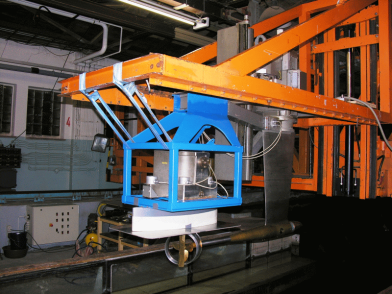
To investigate this problem experimentally, a hydraulic slamming system was developed in the SVA. With this system, pitching, heaving and coupled movements can be introduced with a frequency of up to 2.0 Hz and an amplitude of up to 10 cm on model ships. It can test models with a length of 5.5 m and a moving mass of 500 kg. By measuring pressure variations in the kHz range on up to 30 measurement points, local peak pressures can be identified.


Technical Specifications
Max. Frequency 2 Hz
Max. Amplitude 0.1 m
Max. Model Length 5.5 m
Max. Mass 500 kg
Max. # Measurement Points 30


Context Related References / Research Projects

[1] Fröhlich, M.: Einsatz eines Schwingungsoszillators auf hydraulischer Basis zur Untersuchung der Slammingbelastung von Schiffen, STG-Sprechtag „Schiffe im Seegang“, Hamburg, Oktober 1998

Z Drives

Lorem ipsum dolor sit amet, consectetur adipiscing elit. Curabitur lectus elit, porttitor quis placerat eget, porttitor eget nunc. Aliquam vel ex lectus. Sed ultricies sed nisi vitae faucibus. Integer sit amet dapibus dolor. Proin tincidunt orci a neque convallis tincidunt. Sed consectetur vel ex sit amet euismod. Praesent commodo ex id ligula porttitor semper. Morbi tempus justo id nisl mattis, eu laoreet sapien suscipit. Aenean est lacus, sodales nec varius vel, convallis sit amet nisl. Cras eleifend, ante vel tempus aliquam, tellus orci tristique nisl, nec convallis diam metus at diam. Proin egestas mauris ligula, in elementum ex efficitur eget. Praesent viverra commodo lacus, eget molestie dui molestie sed. Aliquam nec mollis quam. Phasellus euismod consectetur tincidunt. Phasellus sit amet felis elementum, bibendum dolor quis, blandit magna.

Curabitur eu massa vitae turpis laoreet molestie in eu velit. Nunc in condimentum nisl. Suspendisse potenti. Nullam ante ex, varius nec dignissim faucibus, suscipit vel eros. Aliquam condimentum nisi sit amet est vestibulum tincidunt. Quisque nisl enim, tempor in porttitor sed, ornare ac massa. Mauris sed convallis nisl. Aenean volutpat finibus turpis. Ut porta sagittis ligula congue vestibulum.

CP Propeller System

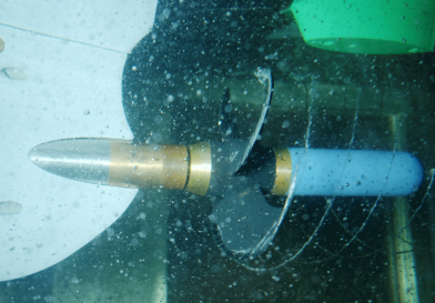
With an adjustable blade hub, the dynamic adjustment of ptich during testing is possible, for example, for stopping manoeuvres. The adjustable blade hub achieves the change of blade pitch with a multiphase motor with two limit switches built in which switch off the engine at ± 30° adjustment. The average pitch is marked on the inner hub. The angle is measured with a potentiometer. The hub is mounted on a carbon ring. The control data and the values of the potentiometers are transmitted via a slip ring assembly.

Main Parameters
Hub Diameter mm 60
Hub Length mm 57
Number of Blades 4
Propeller Diameter mm 250


Flügelverstellnabe_1Flügelverstellnabe_2_small


Context Related References / Research Projects

[1] Steinwand, M.: Optimierung des Stoppmanövers mit Verstellpropellern und Hybridantrieben, 9. SVA-Forschungsforum, Potsdam, 28. Januar 2016