Ducted Propellers
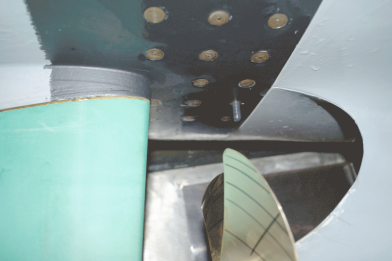
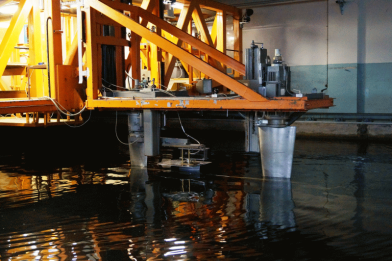
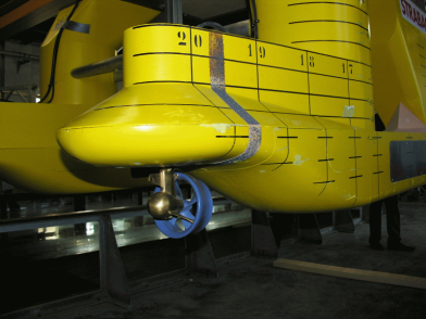
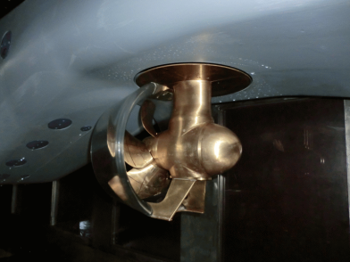
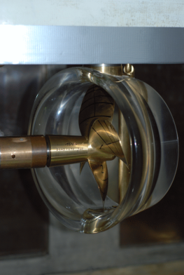
Kempf & Remmers dynamometers are used for propeller drives. The forces at the nozzle are measured with Kempf & Remmers single and multi-component balances that are coupled to the dynamometers.
Main Paramters Dynamometer/Balances for Ducted Propellers
|
|
|
FK1/R35I |
H29/R35X |
H39/R35X |
H39/R37 |
H36/R35X |
J25/R37 |
| Thrust Tmax |
[N] |
* |
400 |
1000 |
1000 |
2000 |
3000 |
| Torque Qmax |
[Nm] |
* |
15 |
50 |
50 |
100 |
150 |
| Nozzle Thrust TDmax |
[N] |
200 |
500 |
500 |
800 |
500 |
800 |
| * Using Interior Drive Dynamometer |
Contra-rotating Propeller
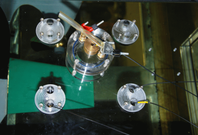
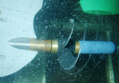
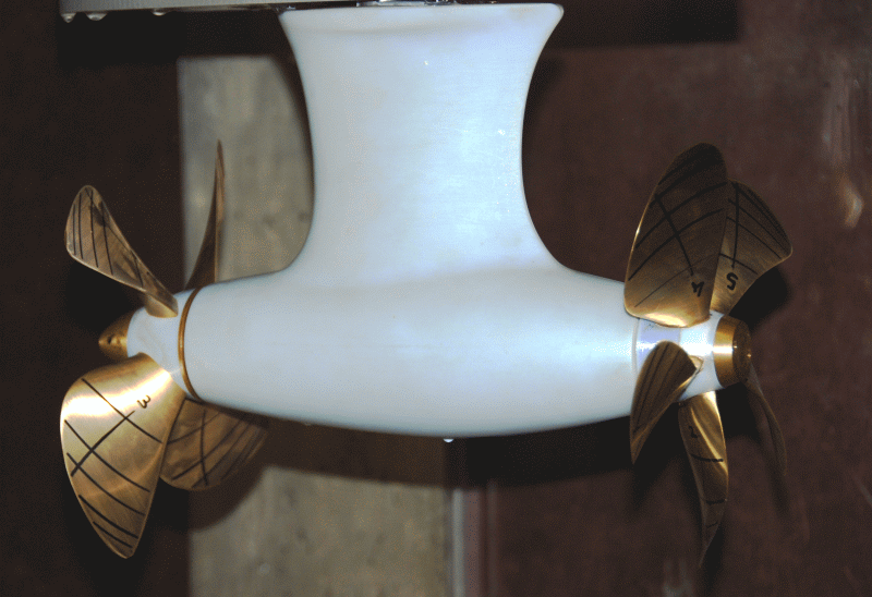
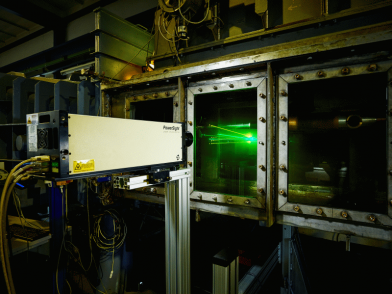
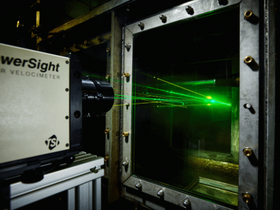
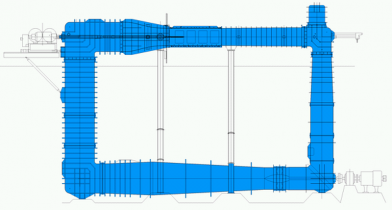
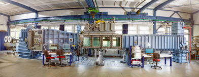
The SVA has the Kempf & Remmers contra-rotation dynamometer R40 for open water and propulsion testing. Open water tests with contra-rotating propellers can also be performed via the coupling of the H29 and H39 dynamometers in the towing tank. For the investigation of contra-rotating propellers, the K15A cavitation tunnel was equipped with J25 and H36 dynamometers from Kempf & Remmers. The dynamometers can be arranged in the measurement section so that measurements with contra-rotating propellers are possible at different distances.
Main Paramaters Dynamometer/Balances for Contra-rotating Propellers
|
|
|
FK4/R40/R35I |
H29/H39/R35X |
J25/H36/R35X |
| Thrust Tmax1 |
[N] |
150 |
400 |
3000 |
| Thrust Tmax2 |
[N] |
150 |
1000 |
2000 |
| Torque Qmax1 |
[Nm] |
6 |
15 |
150 |
| Torque Qmax2 |
[Nm] |
6 |
50 |
100 |
| Housing Resistance TPodmax |
[N] |
200 |
500 |
500 |
Thrusters and Podded Drives
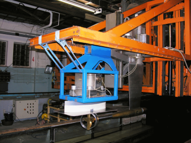
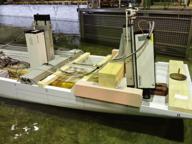
Model tests with azimuthing thrusters and podded drives are a focus of the work of the SVA. For the realisation of measurement tasks in open water, cavitation, propulsion and manoeuvring, different propulsion and measuring systems have been developed by the SVA. The system forces of the thruster and podded drive are measured with 3- or 6-component balances.
Main Parameters Balances for SVA Thruster Dynamometer
|
|
|
|
R37SR1/SR2 |
R37SR3/SR4 |
R37 |
R200 |
| Forces |
Fx1 = Fy1 = Fy2 |
[N] |
200 |
500 |
800 |
1000 |
|
Fz1 = Fz1 = Fz2 |
[N] |
– |
1000 |
500 |
2000 |
| Turntable |
Fx |
[N] |
100 |
100 |
manual |
5000 |
|
Fy |
[N] |
100 |
100 |
|
3400 |
|
Fz |
[N] |
600 |
600 |
|
5000 |
|
Mx1 = My |
[Nm] |
– |
– |
|
500 |
|
Mz |
[Nm] |
15 |
15 |
|
60 |
The drive of the propeller and the measurement of the forces and moments on the propeller are carried out with SVA thruster dynamometers. Thruster dynamometers are available at the SVA for tests with thrusters or podded drives with pull, push, twin and contra-rotating propellers.
Main Parameters SVA Thruster Dynamometer for Single Propeller Systems
|
|
|
Z65/1 – /4 |
Z200 |
Z600/4, Z600/6 |
| Thrust Tmax |
[N] |
50 |
200 |
600 |
| Torque Qmax |
[Nm] |
1 |
7 |
20 |
| Transmission |
|
* |
1.615:1 |
2:1 |
| Housing Resistance TPodmax |
[N] |
200 |
500 |
500 |
| Total Torque QGmax |
[Nm] |
1 |
2.4 |
17 |
| * Drive with an electric motor in the housing |
Main Parameters SVA Thruster Dynamometer for Double Propeller Systems
|
|
|
TP200/1…/2 |
TP400/1…/2 |
CRP400 |
CRP600 |
| Thrust Tmax |
[N] |
200 |
400 |
400 |
600 |
| Torque Qmax |
[Nm] |
7 |
20 |
20 |
20 |
| Transmission |
|
1.1 |
2.1 |
2:1 |
2:1 |
| Total Torque QGmax |
[Nm] |
6 |
17 |
17 |
17 |
Context Related References/Research Themes
[1] Gutsche, F.: Düsenpropeller in Theorie und Experiment, Jahrbuch der STG, Bd.53, 1959
[2] Schroeder, G.: Wirkungsgrad von Düsenpropellern mit unterschiedlicher Düsen- und Propellerform, Schiffbautechnik, 1967
[3] Heinke, H.-J.; Philipp, O.: Development of a skew blade shape for ducted controllable pitch propeller systems, Proceedings, PROPCAV’95, Newcastle, 1995
[4] Schulze, R.; Manke, H.: Propellersysteme mit Ostdüsen“, HANSA, 137, 2, 2000
[5] Schmidt, D.: Propulsionsuntersuchungen mit Einzelpropeller und Gegenlaufpropeller am Modell eines Containerschiffes, Schiffbauforschung 14 1/2/1975
[6] Heinke, H.-J.: Azimuthing propulsion – Experiences of SVA, 6. SVA – Forum „Azimuthing Propulsion – new challenges and chances“, Potsdam, 1998, Schiffbauforschung, 38. Jahrgang (1999) Heft Nr. 1
[7] Kaul, S.; Heinke, H.-J.; Abdel-Maksoud, M.: Hydrodynamische Optimierung von Podded Drives und aktuelle Anwendungen in der Großausführung, 54. Sitzung des FA „Schiffshydrodynamik“ der STG, Hamburg, September 2000
[8] Heinke, H.-J.: Investigations about the forces and moments at podded drives, First International Conference on Technological Advances in Podded Propulsion, Newcastle, UK, April 2004
[9] Heinke, H.-J.: Hydrodynamische Untersuchungen für einen Podded Drive mit HTS-Synchronmaschine, Statustagung Schifffahrt und Meerestechnik, Bundesministerium für Wirtschaft und Technologie, 03. Dezember 2009, Rostock-Warnemünde
