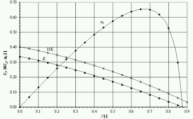
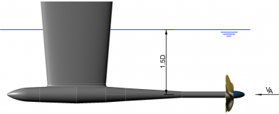
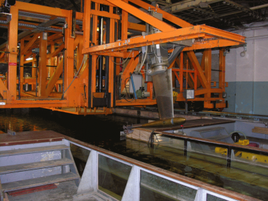
In open water tests the characteristics of the propeller are measured in homogeneous inflow. Open water tests are mostly performed in the towing tank. For this purpose, the SVA utilises open water carriages and propeller dynamometers. In open water carriage FK1 Kempf & Remmers, the integrated inner dynamometer can be used with different measuring ranges to measure with the highest possible accuracy. In addition, the open water carriage can be used to measure forces and moments on the individual blades of the propeller. For this purpose, measuring hubs have been developed for propellers with three, four and five blades. For the investigation of counter rotating propellers, the dynamometer R40 Kempf & Remmers is used. The dynamometer is installed in the open water carriage FK4 and can be driven by one or two motors to examine the counter rotating propellers with fixed or variable speed ratios. Most open water tests are carried out with the dynamometers H29 and H39 from Kempf & Remmers. The dynamometers differ in size and range and are appropriately selected to match the model propeller.
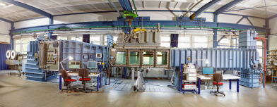
The characteristics of the propeller can also be determined in the cavitation tunnel K15A. The influence of the limited size of the cross section on the flow velocity or the thrust and torque of the propeller is considered in the test evaluation. The SVA uses the method of Glauert [1] to calculate the wall correction. The cavitation tunnel K15A is equipped with the dynamometers J25 and H36 from Kempf & Remmers. The dynamometer H36 can be used to measure the forces and moments on the individual blades of the propeller by means of a measuring hub.
All dynamometers can be combined with single and three-component balances. Thus, the measurement of the open water characteristics of jet propellers or complex propulsion systems is possible. In addition, two dynamometers and balances can be used together to test counter rotating propellers, tandem propellers or other special propulsion systems.
The shaft inclination of dynamometer H29, H39 and H36 can be varied. The dynamometer H39 and H36 can also be equipped with devices for the measurement of transverse and vertical forces of the propeller.
The detailed description of the experimental procedures and evaluation is contained in the documentation of the Potsdam Propeller Test Case (PPTC) [2].
Context Related References / Research Projects
[1] Glauert, H.: Wind Tunnel Interference. W. F. Durand, Aerodynamic Theory, Vol. IV, Berlin 1935, Division L: Airplane Propellers; 296 – 306
[2] smp’11: 2nd Symposium on Marine Propulsors & 1st Workshop on Cavitation and Propeller Performance, June 17 -18, 2011, Hamburg, Germany


