Model Manufacturing
The ship model blanks are made from laminated slabs of abachi wood.
Waterjet Cutting System
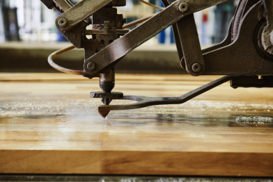
The components are created with computer assistance and manufactured by means of a high-pressure waterjet cutting system (3500 bar). The machine cuts the parts very accurately and efficiently in rapid succession. The water absorption of the cut surface is very low and allows a further processing of the blanks after a drying time of one day. The machine has a working range of 2000 mm x 4000 mm and is also capable of cutting up to 120 mm thick steel.
5-Axis Milling Machine
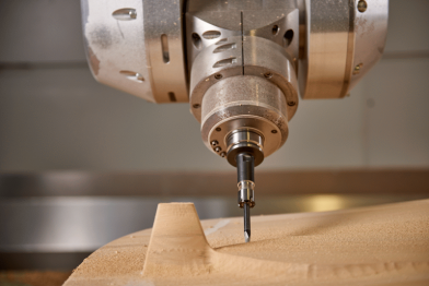
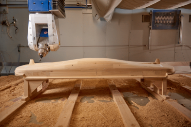
The laminated ship blanks are completely machined on the Huber & Grimme 5-axis milling machine using coarse and fine milling operations, and thereby achieve a nearly perfect surface finish. With a one-time manual surface sanding after the milling process, the model is prepared for further processing. With the use of 5-axis milling machine, the requirements of the ITTC are met in terms of accuracy of model ships (± 1 mm, 0.5 % Lpp). The machine has a maximum working range of 8000 mm x 2500 mm x 1200 mm, a processing speed of up to 40 m/min. and a maximum speed of 24,000 rpm.

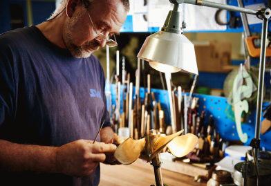
Various machines are available for the manufacture of propellers, appendages and accessory parts.
Automatic Cycles Lathe UT500
For the production of swivel parts (small batches and individual parts) the automatic cycles lathe UT 500 is available. Through the possibility of free-form programming, for example, propeller nozzles, outlets and other parts that are not purely cylindrical can be produced quickly and efficiently on this machine.
Main Paramaters Automatic Cycles Lathe UT500 |
||
| Swing Diameter over Bed | [mm] | 510 |
| Swing Diameter over Cross Slide | [mm] | 340 |
| Swing in Bed Bridge | [mm] | 760 |
| Distance Between Centers | [mm] | 1500 |
| Vertical Travel Distance | [mm] | 680 |
| Max. Turning Length | [mm] | 1140 |
| Travel distance bed Bridge (x axis) | [mm] | 310 |
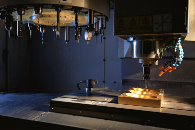
5 Axis Milling Machine UNITECH XV620-5AX
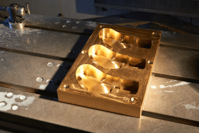
A XV 620-5AX 5-axis milling machine is available for machining of complex components such as model propellers, shaft struts and propeller hubs. The machine has a working area of 650 x 520 x 480 mm³ with a drive power of 10 kW and is well established in the field of precision engineering.
Main Parameters Milling Machine UNITECH XV620-5AX |
||
| x-Axis (Longitudinal Adjustment) | [mm] | 620 |
| y-Axis (Lateral Adjustment) | [mm] | 520 |
| z-Axis (Support Vertical Adjustment) | [mm] | 510 |
| Tool Fitting (DIN 69871) | — | Taper Shank SK40 |
| Input Power at S1 100% | [kW] | 10 |
| Torque at S1 100% | [Nm] | 64 |
| RPM Range | [min-1] | 0 …12000 |
Milling Machine UNITECH VMC1200
The UNITECH VMC1200 milling machine serves to produce components made of metal. This is characterised by its large working area of 1000 x 520 x 480 mm³. The 4th axis, simultaneously controlled, attachments allow for the production of components (drive housings) that must be pivoted during processing.
Main Parameters Milling Machine UNITECH VMC1200 |
||
| x-Axis (Longitudinal Adjustment) | [mm] | 1000 |
| y-Axis (Lateral Adjustment) | [mm] | 520 |
| z-Axis (Support Vertical Adjustment) | [mm] | 420 |
| Tool Fitting (DIN 69871) | — | Taper Shank SK40 |
| Input Power at S1 100% | [kW] | 16 |
| Torque at S1 100% | [Nm] | 60 |
| RPM Range | [min-1] | 0 …15000 |
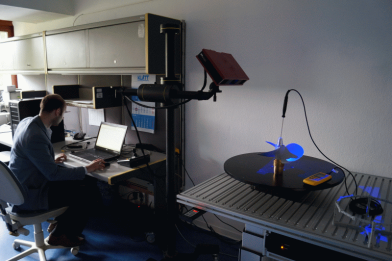
- Accuracy of 18 µm
- Object size with high accuracy (18 µm): 300 x 230 x 300 mm³
- Object size at a lower accuracy (50 µm): 600 x 600 x 600 mm³
- Manual two axes adjustment (lifting table, rotary table)
- Projection of 3D elements
- Automatic report creation
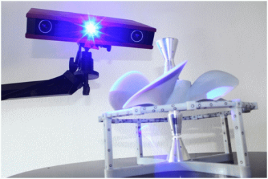
The ATOS Core 300 is used in production and quality control as follows:
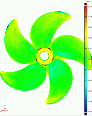
- Scanning of the geometry after milling (while model is still in the milling block). When the predetermined allowance is not reached locally, the milling process is continued.
- Scanning of the model after the removal from the milling block and the evaluation of the target – actual comparison with colleagues of the workshop in order to specify the steps in the manual finishing.
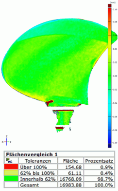
- Scanning of the model after completion, analysis of target – actual comparison, preparation of proof of compliance with the quality criteria and creation of an examination report.
Furthermore, components, test objects and geometries from existing measurement systems are recorded with the 3D scanner and provided for use in new experimental arrangements.

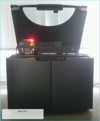
Technical data |
|||
| Max. component length | x axis | [mm] | 340 |
| y axis | [mm] | 340 | |
| z axis | [mm] | 340 | |
| Resolution | Layer thickness | [µm] | 16 |
| x axis | [dpi] | 600 | |
| y axis | [dpi] | 600 | |
| z axis | [dpi] | 1600 | |
| Accuracy | Components >= 50 mm | [µm] | 200 |
| Components < 50 mm | [µm] | 20…85 | |
